3D Printed Rotary Time Tracker for Task Management (Part 1/3)
Overview
3D Printed Rotary Time Tracker for Task Management (Part 1/3)
Full disclosure: This is a continuation from a Hackaday project I started some time ago. I’m finally documenting all the details here. I truly enjoyed designing, developing, and using this little device. However, I now see multiple possible improvements for a second version. This post will walk through the overall concept and the Gray Encoder design. Later in the series, I’ll cover the 3D printing, assembly, and signal processing steps.
Description
Working from home has made it incredibly easy to get distracted on the computer. I like to organize and structure the objectives I spend time on while at my desk.
I've seen those time tracker programs and/or gadgets like Timeflip2 that you can buy suited for this need, but why use waste money when you can hack your own?
Lastly, I didn't really like the rotate a cube for a task. I wanted something more...magical, with magnets of course.
This gadget rotates between different tasks/activities using magnets to lock in place, records the status on the computer, and then can be viewed on a daily basis the distribution of tasks.
Tasks are in a circular pattern, identified by a 3D printed gray encoder inside the device. The LED in the center is filtered through the gray code and read by the photoresistors to identify the status of the task.
Why?
I found myself struggling with structuring my time when the new work from home life began. I don’t think I’m the only one whose gaming desktop has now become their work desktop too! It’s mighty tempting when that StarCraft icon is right next to your Outlook icon. Nevertheless, I needed a solution to structure and compartmentalized my time accordingly. I wanted a sleek way to record my time spent between work functions (meetings, coding, writing, email, and project management) and personal functions (hardware hacking and gaming).
There are tools out there that do this on the software side and hardware side. But why would I overpay someone to do that when I wanted to make an open-source, free solution available for everyone? Also, those devices I saw didn’t use magnets, and I wanted to make something with magnets in it.
Design
The gadget consists of two main 3D printed parts, a base and a top. The base contains three photoresistors, and a spindle in the center with a green LED inside to shine light into the top. The top of the device rests on a spindle in the center with a 608 bearing to rotate freely. Inside the top, there is space for the LED light to shine and reflect off the inside surface to be filtered by a simple 3D printed 3-bit gray encoder (info on a gray encoder: https://en.wikipedia.org/wiki/Gray_code). Light is blocked from the encoder that is in between the light source and the photoresistors, where the signal from the photoresistors can be filtered to a binary code using an Arduino to identify what ‘task/activity is being represented. As I mentioned, I wanted to use magnets in this project, no I needed to use magnets. There was a problem with how to ‘lock’ the task in the correct coordinate, but I was pleased with the rotation along the spindle and wanted the top to be separate from the base. My problem was solved by eight evenly spaced magnets inside the top and bottom translated in between each other with the magnets in a repelling orientation (i.e. North facing North). This ensures that the top spindle will stay fixed in a specific location and is very satisfying to move from one position to another with subtle haptic feedback.
Designing the Gray Encoder Top
Let me start this by saying:
I’m not an expert on anything I’m about to talk about.
But I do think it’s worth having an in-depth look at how I got this device to work and how the Gray Encoder works.
When I first sat down to design the Task Tracker. I had two constraints:
- I didn’t want it to be some rotation cube or dodecahedron like what you can currently get commercially. I also struggle to see how this is different than an accelerometer with some fancy frontend.
- I didn’t want it just to be a ‘knob turn’ There would be plenty of ways for me to just 3d print something on top of some pre-existing knob or dial indicator. Where is the fun in that? That was when I first thought of using photons as my signal. This would allow me to be able to keep the top floating (with magnets, of course) and not reliant on any actual mechanically rotating shaft. So I added an LED and some photoresistors. The two photos below show the proof of concept I was working with 8 digits (3-bit resolution).
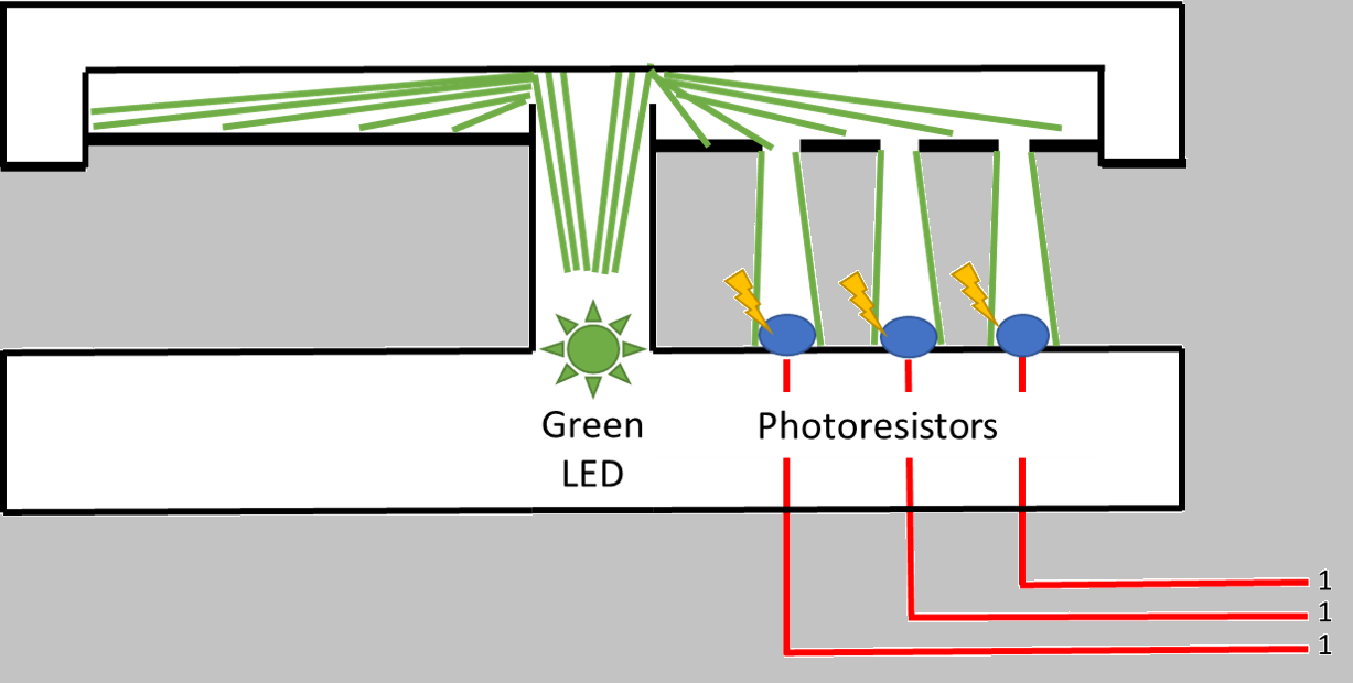
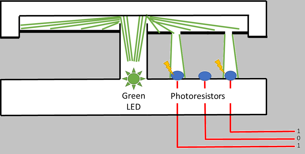
In the first photo, we see that light emits onto all photoresistors sending the value to ‘1 1 1’ or 7 when converted to decimal. In the second photo, the middle sensor is blocked, corresponding to ‘1 0 1’ or 5. Here lies the interesting problem in implementing this practice. The rotation of the dial in the device should correspond to eight specific positions; in ideal conditions, it should just count as position 0, 1, 2, … to 7. Let's see what that looks like in just binary around a circle.
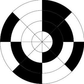
Here white means 0, and black means 1. Starting at the top, going counter-clockwise, we see our immediate problem: ‘000’, 001’, ‘010’ (read from the center of the circle to the outside). Right there. Transitioning from ‘001’ -> ‘010’ means you have to switch two bits at once. If you have an imperfect system (for example light shining through a small slit and detected with a photoresistor) the signal-to-noise ratio is very high, and switching two bits at once can confound results. So we need a system that only turns one bit at once while still being addressable to ensure we know we changed states. Enter the Gray Code (https://en.wikipedia.org/wiki/Gray_code).
New design:
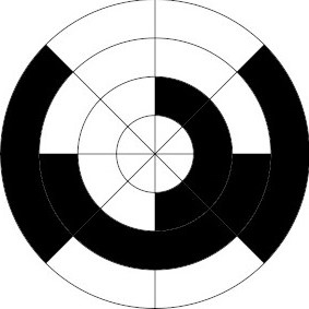
Here, we start in the same sequence: ‘000’, ‘001’, but next is ‘011’. So this next state of ‘3’ is only a one-bit movement away from ‘1’ and this applies for all numbers from 0-7, even 7->0 is very convenient when we want to ensure that we know when a state transition happens.
Lastly, I want to ensure I translate the sensor values to a position that is interpretable back to the human, so I must convert the gray code back to a number. In code, this looks like this:
 1int gray_to_num(int s[])
 2{
 3  int num = 0;
 4  //convert array to int
 5  for (int i = 0; i < 3; i++)
 6  {
 7    num += s[i] << i;
 8  }
 9
10  // Convert Gray Code num to Decimal
11  int mask = num;
12  while (mask)
13  {
14    mask >>= 1;
15    num ^= mask;
16  }
17
18  return num;
19}
The overall code is output to serial what position state the device in, the only thing left for the user to do is to make sure the icons on the lid are aligned with the correct code status, and that the order in the software on the computer to be posted is correct.
2025 Update:
This still is one of my more favorite homemade devices. The application of it for my current lifestyle is somewhat limited as things change over the years. When building this I was using my personal computer for both work and play, nowadays there are much clearer physical divisions of my computer uses. However, I think the complete build is still of great use and can be adapted to many other methods!
In Part 2, I’ll discuss:
- 3D Printing and Assembly: o STL files, recommended printer settings, and instructions on installing the bearing and magnets.
- Sensor Reading and Signal Conditioning: o How to wire the photoresistors to the Arduino. o Practical tips for removing noise or false triggers. o Approaches to calibrating brightness levels for consistent detection. By the end of this series, you’ll have a fully functional rotary time tracker that “clicks” satisfyingly between tasks, helping you stay organized (and letting you enjoy the pleasing feel of magnets snapping together). Stay tuned for Part 2!